 VIETNAM TECHNICAL VIEW
Over the past decade, airbag deployment simulation has become a standard application for finite element codes.
As development begins, the focus is on capturing the effect and improving the outcome of the dummy impact on fully inflated air bags. After that, the deployment kinetics of the folding airbags, different folding techniques, and vent design became more and more important. Given the FMVSS 208 compliance requirement, i.e. out-of-position load cases, it is clear that the interaction between the internal airflow and the fabric airbag construction needs to be included.
Various modeling techniques are shown and their advantages and disadvantages and the effort required to achieve useful results are discussed.

1. Approach to building airbag model:
At the outset of development, the focus was on capturing the effect and improving the outcome of a dummy impact on fully inflated airbags. After that, the deployment kinetics of the folding airbags, different folding techniques, and vent design became more and more important. Given the FMVSS 208 compliance requirement, i.e. Out-of-Location load cases, it is clear that the interaction between the internal airflow and the fabric airbag construction needs to be included. Therefore, the matching algorithms that allow the interaction between the arbitrary air flow and the airbag structure are the main focus.
A common approach and also for other applications that are suitable and successful is to separate the gas domain from finite elements and thus record the flow and strain using the ALE method.
The interaction between the air and the airbag fabric is treated with a fine or restrictive formula.
At the same time, of course, the typical element size decreases, the total number of elements increases, and there are even more sophisticated factors in the constituting laws, dealing with reference geometries and considering porosity, and so on. included in the code. Obviously, all of this is becoming more and more complex with the daily workload of airbag simulation. A sophisticated and very promising particle-based method will be available.
In this article, the authors will outline the development of airbag modeling techniques starting in the early 1990s to the present day. The uniform pressure technique, the ALE method and the recently developed corpuscular particle method will be covered. The results as well as the pros and cons of each method will be presented and discussed in the context of different applications.
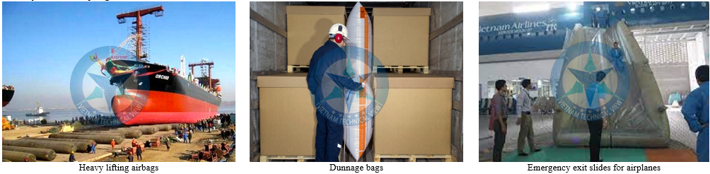
2. Applications of Airbag:


3. Prerequisites to achieve reliable airbag simulation:
To obtain reliable and predictable airbag simulations, a sufficient test database for the airbag fabric is required. Both tight and loose woven fabrics can show differences in mechanical properties, because woven fabrics can resist in-plane shear loads. when it has reached the yarn lock-up angle and the lock angle is much lower for tight weaves than for some loose weaves. Differences in material properties in terms of material orientation can affect the shape of a fully deployed bag.
Recently developed tools for safety analysis provide a material model that combines in-plane shear stiffness properties into warp and weft properties. (weft).
Besides the standard static and dynamic tension test, also known as picture frame tests and biaxial tests, in which a cloth is mentioned loaded with pure shear and biaxial tension, respectively (see Figure 1). From the tests corresponding to the true stress - obtain the true strain curves as depicted in Figure 2. The tests that build the basis of the subsequent validation procedure are discussed in the following section.

MAT_FABRIC is designed for use in airbag applications. During early development, the basic composition model evolved from a fairly simple two-line orthogonal model to the latest implementation with nonlinear biaxial loading and unloading curves. For loading and unloading curve definitions are also available, as well as curve input for porosity. This evolution is captured in the growing number of formulas that can be seen in the FORM parameter. While the earliest formula starts with FORM=0, the newest and most advanced formula is available with FORM=14. Here LS-DYNA expects real stress - real strain data in some curves. input. However, it is clear that these curves need to be extracted from full trials. In addition, younger models (FORM = 4/14) also allow non-orthogonal matter axes to be determined.
In Figure 2, the test data of the biaxial tension test and the picture frame test are depicted (black curve with rounded dots). Test data has been evaluated, stress and strain calculated and used in the validation process based on the detailed customization of the test setup.
As can be seen, the formula older than FORM = 0 cannot capture the unloading and unloading behavior in a proper way.
The much younger formula FORM=4, not only expects nonlinear loads, but loads curves that can capture biaxial behavior well enough. However, it can be seen that compared to the frame test data, FORM = 4 yields a large amount of nonphysical oscillations.
Only the latest development FORM=14 improved with special treatment for clipping data can predict the matching two-axis and frame-test data. It should also be noted that in order to predict the two-axis test correctly, the curve data from the two-axis test must be used instead of the data from the pure tension tests. Otherwise, the first hump in the test data, due to the interaction of warp and fill yarn and subsequent stiffness, will not be reproduced.

4.Overview of airbag deployment algorithms:
4.1 UNIFORM PRESSURE (UP) technique:
Simulation of the deployment of an airbag system was first performed with the FE Method, which simulates the dynamic behavior of the system using explicit time step diagrams. These explicit methods are especially suitable for such complex, highly nonlinear systems because their complex exposure situations during implementation form an initial kink configuration. As a rough approximation of the time-dependent behavior of the pressure inside the bag, the so-called uniform pressure technique was developed in the late 1980s by Wang and Nefske.

In summary, for the UP (Uniform Pressure) technique, there is no arbitrary flow of fluid.
The whole concept is based on scalar thermodynamic equations.
The extensions, which take into account the dependence of the pressure field and the inlet direction (often referred to as Jet), are based on a simple assumption. It is also possible to take into account the gas mixture (called a hybrid gas generator) or the temperature dependence of specific heat coefficients.
The calculation time may be neglected compared to the calculation time required for the structural operation of the airbag.
Inlet gas flow values (mass fluxes and temperature time values) are usually determined by in-tank tests combined with additional techniques for estimating temperature.
The main shortcoming of this traditional method of airbag deployment: It is a strongly simplified process model, which in particular ignores the local fluid effect. Although this is of minor importance in the ordinary case, when a mannequin or passenger is hit by an airbag in a situation where the airbag is almost fully deployed, the situation is different in the case of Out of Position (OOP) load matching. Here, a dummy or passenger is exposed to the airbag in a much earlier stage of deployment and a physically accurate flow situation model is needed. The same holds true for studies of deployment sequences, for example for curtain bags.
4.2 ALE approach to simulate airbag deployment:
To model the gas dynamics accurately, customization of both, the volume of air surrounding the airbag and the inlet gases, and the coupling forces are needed. A very elegant mathematical description of both field equations can be realized through the Lagrangian Eulerian (ALE) arbitrary concept.
In the ALE concept an arbitrary approach that allows a combination of Eulerian and Lagrangian descriptions is used. In a Lagrangian system the observer would move with the material while in a purely Eulerian description the observer is fixed in space and the matter points are moving through a static lattice of particles. fixed point. In the ALE-based approach, the observer can follow an arbitrarily defined path in space. It is clear that the two extreme cases of the more general ALE method are the classical description of the Eulerian grid, commonly used in pure flow problems, and the pure Lagrangian description, which is commonly used in problems. structural math.
Mathematically, an arbitrary reference domain leads to an additional term in the conservation laws. In the numerical algorithm, an additional set of equations must be solved, since the dynamics of the moving grid points have an impact on the arbitrary problem, shown in Figure 3b. In the following conservation laws are being given. The entire set of equations.
What can be done with ALE:
It is beneficial to use ALE to model: gases – gases, liquids – fluids, large/bulky solids (with great deformation)
Often these parts are contained in or bound by other parts. In many cases, modeling these structures in a Lagrangian fashion can also be beneficial.
Interaction between Eulerian / ALE – and Lagrangian division (FSI)
Applicable to airbags: Few and structures (Lagrangian Finite Elements), Inflated and Ambient Air (ALE)

4.3 Corpuscular method to simulate airbag deployment:
Basic concept:
The static pressure at volume V is a direct function of the total translational kinetic energy of the molecules in the gas. The pressure p is created by the molecules colliding with the boundary of the volume.
There are usually 1023-1024 molecules in an inflated air sac, and one cannot deal with individual molecules in a numerical model. That is why it is common to return to the continuous gas treatment method and use numerical methods such as FEM, SPH or EFG. However, the continuous gas treatment creates geometrical difficulties in the gas-fabric contact and in handling the gas flow through the narrow openings
The new method in LS-DYNA for airbag simulation is unique in that it uses a molecular model of air flow. That is, the gas is modeled as a collection of individual particles. This was done by having each particle represent many molecules. The expected pressure is matched by ensuring that the sum of the translational kinetic energies of the particles is correct.

Note that particles, like molecules, can store some energy in the form of rotation and vibration. This is necessary to have an accurate ratio between Cp and Cv and, therefore, also for an accurate behavior of the gas during expansion/compression.
Assigning particles with the same properties as molecules in classical gas theory, one automatically matches the pressure drop during adiabatic expansion (pV-work).
Limit:
Deviations from thermal balance aren't handled perfectly, but seem good enough for airbag analysis. One must also ensure that the number of particles is not too low, the number depends on the volume to be filled. In paragraph 5.2, this issue will be studied in detail.
Porosity, vent hole and blockage:
Porosity properties were obtained directly from MAT_FABRIC (FLC and FAC curves) as usual for UP and ALE bags. Ventilation holes must be physically modeled as patches of shell elements. This is necessary to calculate the correct bag volume and correctly handle the outside atmospheric pressure (usually 1bar). Obstruction (both vented and spongy) can be taken into account, by setting a flag in the input deck.
4.4 Compare UP, ALE and C methods:
Some of the following airbag examples show the specific advantages and disadvantages of each method.
Example 1: Compare the methods taken as an example of a flat air bag with a perpendicular air inlet
An airbag opens to a square. The bag is inflated (with two separate mass flow curves, constant temperature, see Figure 5) with UP (*AIRBAG_HYBRID_JETTING), ALE (AIRBAG_ALE with 27000 cells) and new method C (AIRBAG_PARTICLE with 10000 particles).
To obtain equivalent results, the injection pump-driven option was used. In the present example, we only examine qualitative results, i.e. the shape of the airbag at certain time steps. Experimental results are not available.
In Figure 7 different shapes of airbags deployed with all three methods are shown at different time steps.

5. Folded Airbags:
Folding styles:

Elements can be stretched nonphysically due to folding.
To remove the nonphysical stress caused by the original kink shape, use *AIRBAG_REFERENCE_GEOMETRY to specify the node coordinates of the incompressible airbag.
6. Driver side airbag deployment simulation:
The folded airbag cushion is housed in a box with a canister with Y-tear pattern cover as shown in figure 11. The tear seam mechanism uses a material failure element. failure of element) requires a smaller time step than the constraint failure mechanism, and it can help reduce CPU computation time.
Tear seams are defined as taking advantage of constraints with failure.
Dynamic relaxation is carried out as a pre-simulation until the internal energy of the folded airbag cushion in the box reaches a sufficiently steady state as shown in Figure 12.
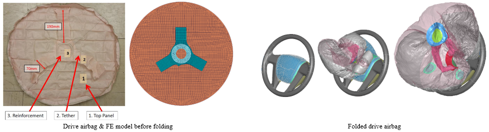
6.1 Driver side airbag module:
The folded airbag cushion is housed in a box with a canister with Y-tear pattern cover as shown in figure 11. The tear seam mechanism uses a material failure element. failure of element) requires a smaller time step than the constraint failure mechanism, and it can help reduce CPU computation time.
Tear seams are defined as taking advantage of constraints with failure.
Dynamic relaxation is carried out as a pre-simulation until the internal energy of the folded airbag cushion in the box reaches a sufficiently steady state as shown in Figure 12.

During this stage, the parameters related to the definition of contact between the DAB housing and the airbag fabric are adjusted.
These three drop tests and simulations with the uniform pressure method contribute to the quick confirmation of parameters related to gas leakage, contact, stress and variation. stress and strain.

Drop testing is a widely used tool for airbag performance validation. A good correlation between the actual tests and the simulation model of the measured acceleration was obtained with the conventional FE airbag model based on the uniform pressure method.
Although the airbag model is reliable and predictable for a fully deployed state that provides confidential results in the interaction between the airbag and the occupants, in the case of occupant injury assessment sitting in the airbag hazard area or out of position and the airbag module design is different for occupants in the OOP (Out-Of-Position) or DAB cap, the drop test is not a confirmation tool. Fit.
In situations outside of the OOP position, airbag shape and region-specific response over time are important factors in occupant injury.
Various dynamic testing methods with head form, pendulum, or matrix of load cells have been developed to provide better evaluation data for Airbag deployment simulation model.
The pressure distribution inside the airbag provides an insight into the airbag module and a direct comparison between the testing and the flowing gas integrated simulation, while the simulation uses the impactor. (impactor) has an additional interaction between the airbag and the impactor.
For this purpose, airbag static deployment tests were performed to obtain the pressure distribution inside the folded airbag and the covered airbag. ).
Folding and covered airbags were modeled by the corpucular method using 200 000 particles in the LS-DYNA for air flow, based on the model previously validated with the pressure method. uniform pressure method and drop tower tests.
Distance and error are also measured for airbags in the up and forward view.

The good correlation of pressure peaks observed in early deployment (approximately 5ms) and pressure levels at full deployment (approximately 25-30ms) of simulation is in agreement with test data on the whole.
The kinetics during the airbag opening of the simulation coincided with the 15ms pre-test data similar to the folded airbag simulation results.
Video of static simulation of driver's side airbag: ***************************
7. Passenger airbag deployment simulation:


The passenger airbag (PAB) module is part of the passive safety system on most vehicles.
Specific regulatory, consumer and OEM requirements affect the development of passenger airbag modules.
The following categories summarize those requirements:
The integrity of the module must be ensured in order for the airbag to deploy reliably from the module.
Open the IP cover: During the deployment process, the airbag interacting with the IP cover will inflate with a certain reaction force.
Avoid damaging the windscreen during the deployment of the airbag
Off-position load cases. The US legal requirement considers load cases where the human dummy is not in the nominal position. In such situations, the airbag interacts with the dummy during deployment. Do not exceed dummy values during airbag deployment.
In Position load cases: The limited performance of the airbag reduces false positives in frontal crash situations.

The physically accurate FE PAB model allows prediction of physical parameters such as: pressure inside the airbag, volume of the airbag, and force to the airbag. Reaction forces to the surroundinging parts of the airbag.
To achieve this goal, all important physical effects affecting the overall performance of the airbag must be captured:
7.1 Airbag contour and internal components:
The shape of the airbag is controlled by the contour of the IP (contour of the IP) and the angle of the windscreen. Furthermore the available packing space and inflatable efficiency affect the contour of the shape.
Straps are applied to reduce airbag volume or change shape. The so-called Calzone is a piece of several cylinders that are wrapped around the inflator to direct air into the outer regions of the airbag. The belt and calzone are shown in the picture.

7.2 Airbag folding:
Learn the folding process in detail and take the time to set up the actual folding airbag module.
The folding airbag must have no crossing and penetration points and must not exhibit a high initial energy level.
A virtual folding table is set up to simulate the folding process in detail in advance.
Figure 18 shows some intermediate steps of the folding simulation process:
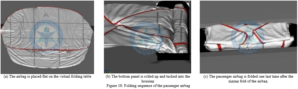
Figure 19 shows a model and snapshot from the deployment simulation. The rotation of the entire module around the car's crossbeam, and deformation due to pressure and reaction loads can be seen in the simulation.

The folding airbag cushion pattern is located inside the case. In detailed models, solid elements are required for other parts of the module. A minimum of three layers of elements per thickness is common for housing walls or enclosures.
The material tag for tear lines includes a failure criterion to represent proper opening behavior.
7.3 Inflator data:
The inlet data of the inflator must be verified. The general approach is Tank testing. The inflator is placed in a tank of a predetermined volume, a sensor measures the pressure inside the tank after the inflator is energized.
The measured p(t) curve is used as input along with the gas composition to generate the mass-time flow and temperature-time curve. The gas composition, mass flow and temperature curves serve as inputs for the simulation.
Furthermore, the deployment of air into the airbag cushion must be modeled. Therefore, capturing the air flow into the airbag cushion is very necessary. It must be ensured that the air flow is actually working, starting from the inflatable nozzles to the adjacent components.
So the airbag is deployed step by step. The uniform pressure approach is not enough for that, because it applies the same pressure throughout the airbag equally. Instead the CPM method in LS-DYNA allows the requested behavior. Gas molecules are discretized with a limited number of average gas characteristic lattice particles.
To give an indication of the correlation of the detailed models, the sample counterforce predictions are compared with the trials. This impulse is measured by a load cell and can result in several kilo Newtons. Examples are lapel pleats and roll pleats. Hardware size is converted into parameters of these tools. Figure 5 shows several steps of folding simulation: (a) folding table with tools, (b) and (c) illustrating sections of flap and roll folds. The final step is to loosen the FE grid, resulting in a non-intrusive energy-stable grid. To model this effect, the IMOM option of the CPM method is enabled. It assigns the reaction force of the outlet gas at the nozzle to the inflator. The torques and forces are transmitted into the inflator and thus through the screws into the housing.
7.4 Define airbag seam leakage:
In the LS-DYNA several gas leak options are available. here the gas leak level depends on the pressure rate (pressure rate) EVOPT = 7 or 8 in the MAT_FABRIC tag used. This allows the function m*(p) to be defined as input for leakage through seams and/or fabric for a specified part.
Figure 20, the test device for determining the mass flow versus pressure function is shown.
We define an exact known contour in a simplified airbag. Make sure that no other leaks occur. Now we determine the pressure that will inflate the airbag.
During the entire injection process, gas leaks throughout the seam. As soon as the working pressure is reached, the pressure regulator will precisely fill the leak in the airbag line. In volumetric flow measurement, the gas flow over time is measured. We will re-implement this method in 0.05 bar increments for all critical pressure levels achievable during the airbag deployment phase. All these values can be converted to the required m*(p) function for the code.

7.5 Model correlation:
Test procedures have been defined, each for a specific period of time in the implementation:
• 0 – 10ms after ignition gas: Here mainly the reaction force from the airbag on the housing and IP cover is concerned.
• 10 – 40ms after ignition: After opening the hood, the airbag deploys and, depending on design, also hits the windshield.
• The airbag then interacts with the dummy in what is known as an “Out – of – Position” load case during which what is commonly known as an “In-Position” load case. The airbag was fully deployed and the dummy was retained by the airbag.
8. Side curtain airbag model (SCAB) simulation:
This study introduces a method of modeling side curtain airbags (SCAB) with complex structure, resulting in accurate deployment simulation.

Target:
To clarify and define the dominant model parameters during SCAB deployment and pressure-time history
Develop a SCAB modeling approach applied to the virtual development process for the history of component testing's impact deceleration.
Research Methods:
Step 1: Define the inflator inlet attributes (INF) and vaair as the airbag
Step 2: Survey and clarify the dominant model parameters by simple SCAB model consisting of simple cells with smooth air flow.
Step 3: Determine the parameters of deployment time as well as the pressure history over time.
Step 4: Compare and validate with the impactor reducer stroke history in component testing with mass production SCAB.

The deceleration stroke history and simulated deployment geometry are suitable for crash testing.
The mesh size and time step of the modeling parameters have a significant influence on the deployment time and pressure.
![]()
Video results of the research process and the simulation of the airbag deployment test performed by Viettechview:
We provide engineering services for numerical analysis and simulation software integration in your CAE environment.
Thank you very much to everyone who has taken the time to follow these content. Looking forward to everyone's cooperation.
Tel: (+84) 363 999 110
Email: viettechview.kh@gmail.com
1. Đào tạo
0344453359
![]()
![]()
![]()
2. Sản phẩm
0344453359
![]()
![]()
![]()
3. Dự án
0965.985.960
![]()
![]()
![]()
1. Đào tạo
0344453359
![]()
![]()
![]()
2. Sản phẩm
0344453359
![]()
![]()
![]()
3. Dự án
0965.985.960
![]()
![]()
![]()


